Substrate repair is the work that nobody itemises until something goes wrong. Resin coatings, PU-cement, microcement — none of them bridge cracks, fill hollow areas, or restore profile to a damaged substrate. Six categories of repair must be addressed before the first primer goes down. Miss any one and the failure shows up in the finish floor within months, not years.
The six repair categories
Every substrate inspection should produce a punch list across six categories. The work that follows is governed by EN 1504 (parts 1–10) in the European market and by ACI 562 / SDR / 318 in North America. Reference your manufacturer's TDS for product-specific compatibility — many resin floor warranties require specific EN 1504-3 or EN 1504-2 grade products to be used in repair.
1. Crack injection (active and dormant cracks)
Sikadur-52 Injection · SikaFix HH · Mapei Eporip · MasterInject
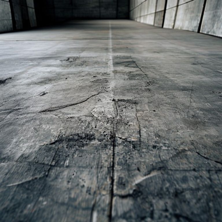
What: Cracks wider than 0.3 mm in the substrate must be filled before resin application. Hairline cracks under 0.3 mm can be bridged by some coatings; cracks above this width will telegraph through to the finish.
How: Dormant cracks (no future movement) are injected with rigid epoxy (Sikadur-52 or equivalent). Active cracks (continued movement expected) require flexible polyurethane injection (SikaFix HH) — these cracks will move; epoxy will simply re-crack at the same line.
Critical detail: Distinguishing active from dormant cracks is the engineer's call. If you cannot determine which type a crack is, default to PU-flexible repair — it covers both cases. If the structural engineer specifies a structural crack repair, that takes precedence over the floor finish decision.
2. Spall and break-off patching
SikaTop Armatec · Mapei Planitop family · MasterEmaco repair mortars
What: Surface spalls (broken concrete chunks, edge fractures, joint corner failures) must be patched with a structural repair mortar — not with the topping that will become the finish floor.
How: Saw-cut a clean perimeter around the spall (minimum 6 mm depth to avoid feather edges). Remove broken concrete to sound substrate. Apply EN 1504-3 grade structural repair mortar in lifts no thicker than the manufacturer's TDS allows. Cure to design strength before any topcoat installation.
Critical detail: Feather edges (zero-thickness perimeters) are the most common spall-repair failure. The repair mortar at zero thickness has no mechanical key and pulls away within months. Always saw-cut a vertical perimeter.
3. Hollow-area injection
SikaGrout · Sikadur-42 · MasterFlow grout systems
What: Hollow areas under the slab surface — typically caused by inadequate substrate compaction during the original pour — are detected by sounding with a chain or steel rod (different sound from solid substrate). These voids must be filled before resin coating, or the surface will deflect and crack under load.
How: Drill injection ports through the surface into the void (typical pattern: 600 mm grid). Inject fluid grout (cementitious or epoxy depending on void size and substrate type). Continue injection at each port until grout returns visibly at the adjacent port, indicating the void is filled. Cure to specification before coating.
Critical detail: Hollow areas are commonly missed during substrate survey because they are invisible. Sound the entire floor before coating — three minutes per square metre with a chain is cheap insurance against an expensive failure.
4. Joint preparation and respect
Sikaflex sealants · SikaSwell stop-strips · Joint backer rod
What: Every structural joint, expansion joint, and isolation joint in the substrate must be honoured at the finish floor surface. Bridging a joint with monolithic resin is a guaranteed crack along the joint line within the first temperature cycle.
How: Clean the joint of debris and loose material. Install backer rod to control sealant geometry. Apply movement-accommodating sealant (typical: Sikaflex elastomeric polyurethane) sized for the expected movement. At the resin floor application, the joint must be continued through the finish — never resin-bridged.
Critical detail: Some specifiers try to hide joints by bridging them with mesh and fibreglass. This works for small movement (less than 0.5 mm) and fails reliably for anything larger. Discuss the joint as a design feature with the architect — a clean visible joint reads as deliberate, a bridged joint that has cracked reads as defect.
5. Contamination removal
Mechanical removal (grinding, shot-blasting) · Solvent cleaning · Detergent + scarification
What: Oil, grease, curing compound residue, paint, mastic, old coatings — all must be removed to clean substrate before profile preparation. Resin coatings will not bond through contamination; they will appear bonded for weeks or months and then peel.
How: Oil and grease — mechanical removal preferred over solvents. Shot-blasting alone is insufficient for petroleum contamination — the petroleum penetrates the concrete and continues migrating out for weeks after surface removal. Multi-step removal: shot-blast surface, apply emulsifier, water-flush, repeat. Cured curing compounds: mechanical scarification is the only reliable method.
Critical detail: Test for residual contamination with a water-drop test (water beads = contamination still present). Resin coating warranty requires this verification.
6. Exposed rebar treatment
Sika FerroGard · SikaTop Armatec 110 EpoCem · Master ProtectoCem
What: Where surface spalls have exposed reinforcing steel, the rebar must be cleaned of rust and treated with anti-corrosion primer before the repair mortar is placed over it. Skip this step and the rebar continues to corrode under the new finish, eventually delaminating it.
How: Mechanically remove rust (wire brush, needle gun, or sandblast). Apply EN 1504-7 grade anti-corrosion coating to all exposed rebar surfaces — Sika FerroGard or equivalent migrating corrosion inhibitor. Cure to manufacturer's TDS before structural repair mortar placement.
Critical detail: IL coastal projects have elevated chloride content driving rebar corrosion. See coastal chloride preparation for the parallel substrate-side chloride remediation that must precede finish floor specification.
Order of operations
The repair sequence is not optional. Each step depends on the previous:
- Substrate survey (visual, sounding, moisture, contamination tests)
- Joint identification and marking (before any other work)
- Contamination removal (oil/grease/coatings)
- Crack identification, classification (active/dormant), and injection
- Hollow-area injection
- Spall and break-off patching (after hollows are filled — order matters)
- Rebar treatment where exposed
- Joint preparation and sealant installation
- Surface profile preparation (grinding, shot-blasting per ICRI CSP requirement)
- Final substrate moisture verification (ASTM F2170)
- Resin or microcement primer application
Documenting the repair
Every repair listed above generates documentation: substrate survey notes, crack-mapping drawings, hollow-area sounding records, injection records (per crack and per hollow with batch numbers), spall patch photos, joint installation records, contamination removal verification (water-drop test photos), rebar treatment records (per location), and final substrate moisture readings. This documentation is the warranty's evidentiary base. Without it, claims are unenforceable.
Continue reading: Six mechanical preparation methods · ICRI CSP profile guide · Moisture testing · Pull-off adhesion test.
Sources
- EN 1504 (parts 1–10) — Products and systems for the protection and repair of concrete structures.
- ACI 562 — Code Requirements for Assessment, Repair, and Rehabilitation of Existing Concrete Structures.
- Sika repair-products portfolio (Sikadur, SikaTop, FerroGard).
- Mapei repair-products portfolio (Planitop, Eporip, Mapegrout).
- ICRI 320.5R — Concrete Crack Repair guidelines.